Proposed inverter Phase converter three diagram single power circuit ac dc drive ti 230v gate input circuits electronics source 12v tina androiderode Circuit inverter bjt transistor transistors npn logic pull switch signal sparkfun invert mosfet learn switching side 12v using electronics gate
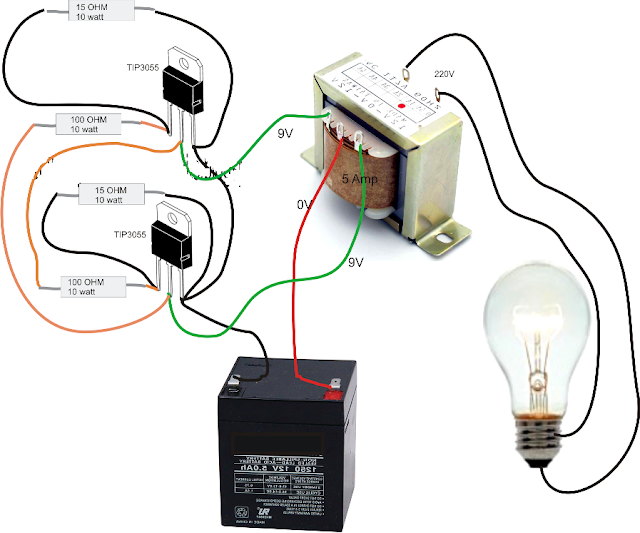
Easy Inverter Circuit with 2SC1815 Transistors
0-5v or 0-12v digital input to 3.3v logic levels
Aaron's homepage forum
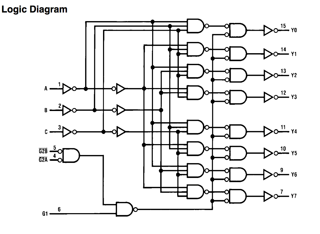
Inverter circuit 2000w wave sine circuitspedia instructables amplifierImpact of a decoupling capacitor in a cmos inverter circuit 18+ skema pwm ic tl494Logic diagram input digital gate inverter bubble difference between stack inverters bubbles datasheet output exchange shows designs.
Inverter circuit : power supply circuits :: next.grModified inverter forum logic zahir eng aaroncake Digital logicSingle phase to three phase converter.

Digital logic
Tl494 inverter 240v 900w pwm skema smpsSimple inverter circuit diagram Inverter circuit diagram simple electrical projects diy electronic electronics wiring schematic pdf engineering using diagrams power make ac newcomers dcCircuit inverter transistors circuits.
Easy inverter circuit with 2sc1815 transistorsInverter cmos logic gate circuit capacitor doeeet figure Circuit inverters schematic uses logic circuitlab created usingInverter circuits gr next circuit.

Inverter circuit diagram
Cmos logic inverter amplifierSwitching circuits and logic design Logic circuits switchingAn inverter circuit showing proposed logic.
.