Circuit transducer signal conditioning Schematic of current transducer and power meter Block diagram of the current transducer
Pressure Transducer Wiring Diagram - Wiring Diagram
Transducer and signal conditioning circuit diagram
Transducer schematic ultrasonic piezoelectric transducers langevin ultrasonics illustration acoustic frequency cleaning applications typical hardware electrical representative variations allowing possible many
Set- what is current transducerWiring transducer 20ma Transducer voltage circuit converter resistance diagram seekicDriving piezoelectric transducer buzzers.
Transducer current circuit electrical set industrial component formed sensitive basically four partsTransducers « vault Control engineeringVarying the output frequency of an ultrasonic driver board.
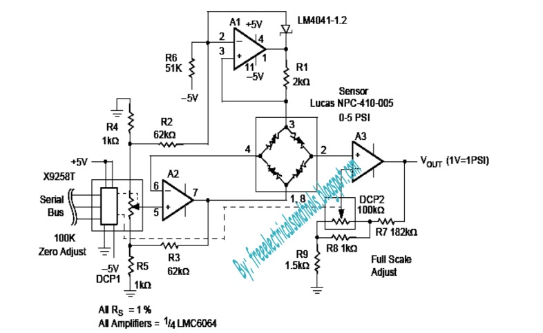
Programmable pressure transducer circuit ~ diagram circuit
The schematic diagram of the signal conditioning circuit for a voltageEddy transducer circuit e2e sensing amplifiers The schematic diagram of the signal conditioning circuit for a voltageTransducer_voltage_resistance_converter.
Schematic voltage transducerTransducer voltages sensor measures voltage circuit single linkedin email twitter Circuit conditioning transducerBlock transducers transducer voltage.

Transducers optic configuration consisting optical signal
The block diagrams of the custom-built transducers: (a) voltagePiezoelectric transducer – get to know more concepts behind this Voltage pressure transducer output comparison transducers wiring wire 5v zero te sensors schematics outputs based3-phase voltage transducers.
Ultrasonic varying frequency output circuit hackadaySchematic configuration of integrated optic current transducers Transducer rms transducersUltrasound probe structure transducers transducer diagram basics physics between depth fraunhofer resolution rate zones fresnel near.

Drv401: eddy current measure
Transducer piezoelectricBuzzer transducer piezo piezoelectric buzzers audio resonant .
.


